

Grid-Forming & Weak-Grid Customization
grid-forming VSG control and weak-grid adaptive microgrid engineering for weak grids at long feeder ends, mining areas and regions with high renewable penetration.
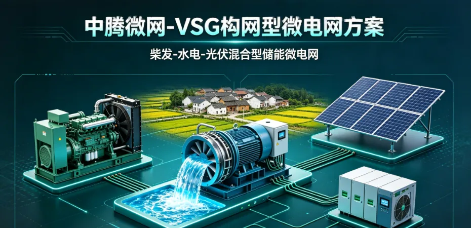
Grid-forming customization: building frequency and voltage at the end of a weak feeder
Long radial overhead feeders, remote mountainous grids and islanded sites share the same signature: a low short-circuit ratio, large voltage swings and trips as soon as renewable penetration rises. Conventional grid-following converters rely on a phase-locked loop and can actually aggravate oscillation there. A grid-forming converter behaves as a voltage source, using VSG virtual-synchronous-machine control to create frequency and voltage and inject virtual inertia — so the battery becomes the machine that holds the grid up.
- SCR ≥ 1.5Operating point our grid-forming designs remain stable at
- below 20 msTransfer and fast island detection
- Inertial responseVSG virtual inertia damps frequency steps
- Ride-throughCustomizable low-voltage ride-through curves
1. First question: how weak is your grid?
Three indicators decide whether grid-forming is mandatory: short-circuit ratio, voltage deviation and any history of oscillation. Two of three means rethink.
Stiff grid
Fault level far exceeds the plant rating.
- SCR above 10; voltage barely responds to output
- Standard grid-following converters behave well
Weak grid
Long, thin conductors; low terminal voltage.
- SCR around 2–3; output changes visibly move voltage
- Parallel converters can fall into control-coupled oscillation
Very weak or islanded
Storage must create the reference itself.
- SCR below 2, or no upstream support at all
- Grid-forming control with its own primary frequency response
2. Following versus forming
In one line: a grid-following unit is a current source that needs somebody else's voltage; a grid-forming unit is a voltage source that provides it.
| Aspect | Grid-following | Grid-forming |
|---|---|---|
| Role on the grid | Tracks grid phase through a PLL | Becomes the reference by creating voltage and frequency |
| Weak-grid behaviour | Loses stability as SCR falls | Remains stable at very low SCR |
| Inertia and droop | Needs added frequency support | Inherent virtual inertia and droop |
| Black start | Not supported | Can energise load and build the system |
| Paralleling | Synchronisation depends on the grid | Droop shares the load between units |
3. Six engineering essentials
Assess SCR and strength first
Divide fault level at the point of connection by total converter rating. Everything downstream — necessity, overload requirement, control tuning — depends on this number.
Tune inertia and droop together
The inertia constant sets the rate of change of frequency, the droop coefficient the steady-state offset. Both must agree with the genset governor, or the two plants will fight over load.
Reactive support and impedance shaping
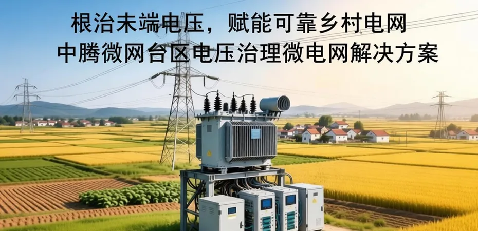
Weak lines often have a low X/R ratio, coupling active power into the voltage. Virtual impedance and reactive control decouple them and suppress voltage rise at the far end.
Genset coordination
Storage takes the instant-to-instant swings while the genset carries average power in its efficient band, avoiding low-load carbon build-up.
Paralleling and circulating current
Multiple forming units need harmonised droop and line-impedance matching to suppress zero-sequence circulating current and power oscillation.
Islanding and seamless transfer
An STS moves between connected and islanded states while grid-forming storage instantly takes over the voltage, so critical load never sees the disturbance.
4. What we calculate
5. Applications
| Scenario | Main symptom | Recommended approach |
|---|---|---|
| Rural feeder end | Long line, low voltage, unbalance | Grid-forming storage with reactive support, isolation transformer where needed |
| Island or remote cluster | No or negligible main grid | Storage forms the bus; genset supplies energy |
| Mine captive network | Large induction-motor starting surges | Grid-forming with overload margin plus soft starting |
| High renewable share | Voltage excursions from variable output | Grid-forming regulation and active-power smoothing |
6. Recommended platforms
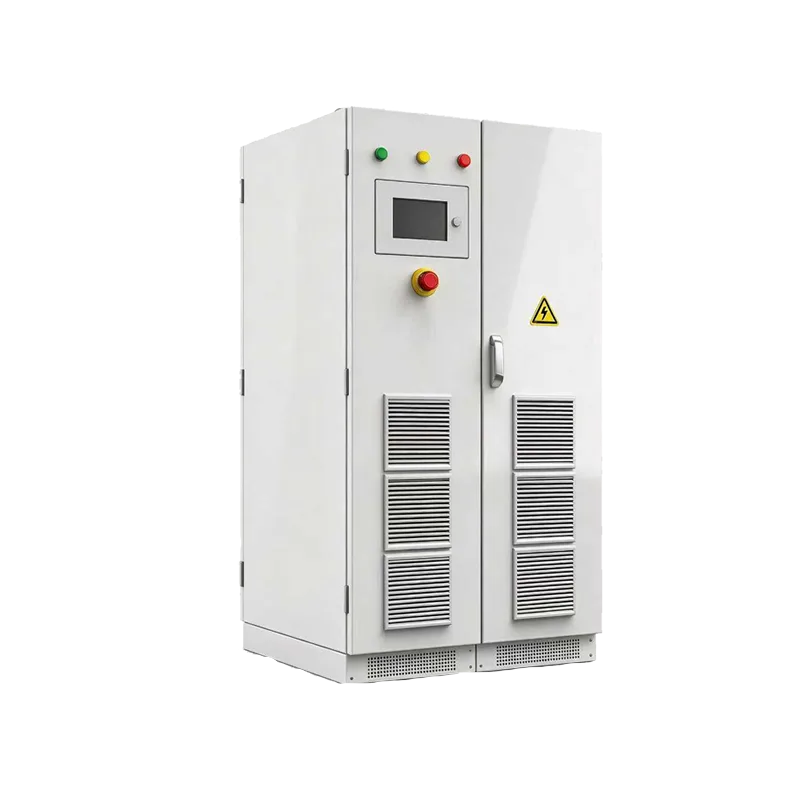
Hybrid inverter with isolation transformer
- IsolationBuilt-in, improves earthing and immunity
- TransferIntegrated switching unit
- ParallelingMultiple units supported
- EnclosureIP54
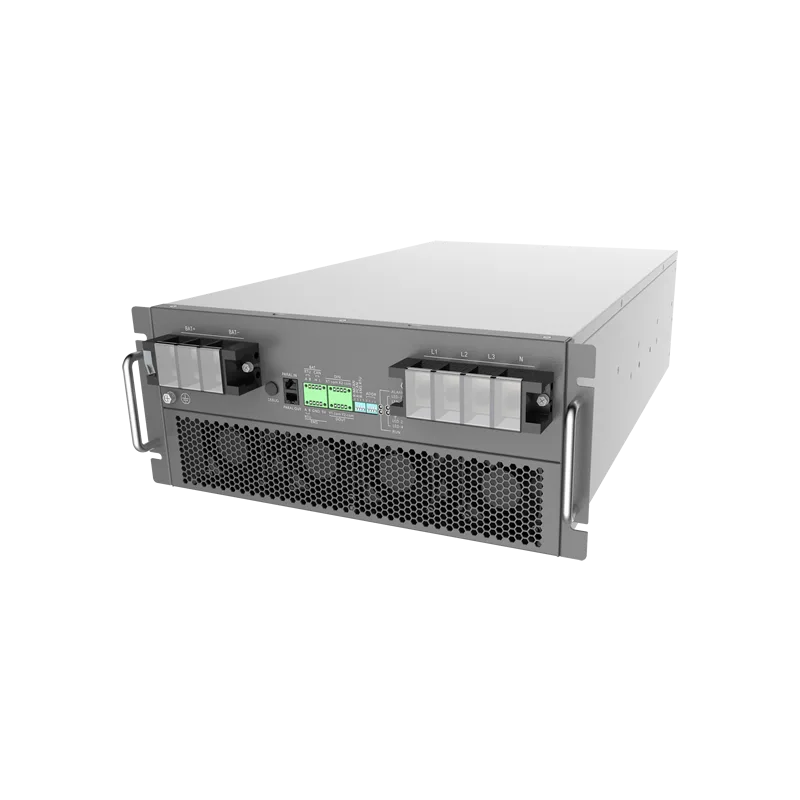
Microgrid storage converter
- Rated power125 kVA
- ControlGrid-forming / grid-following modes
- Transferbelow 10 ms
- Peak efficiency98.5%
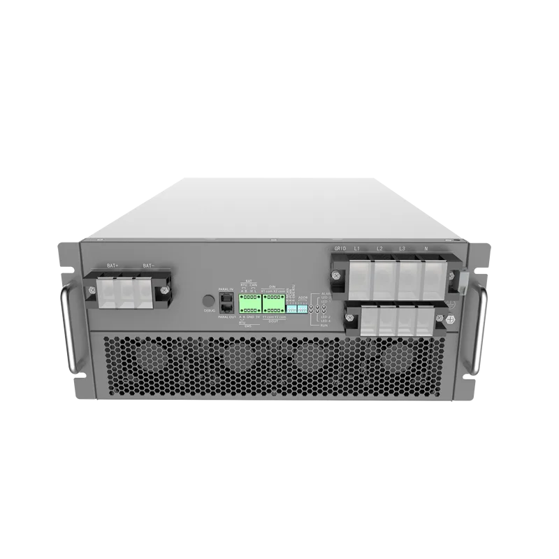
Compact microgrid converters
- TransferBuilt-in fast switching
- ParallelingMultiple units supported
- Genset hybridSupported
- Use caseFeeder ends, islands, farms, villas
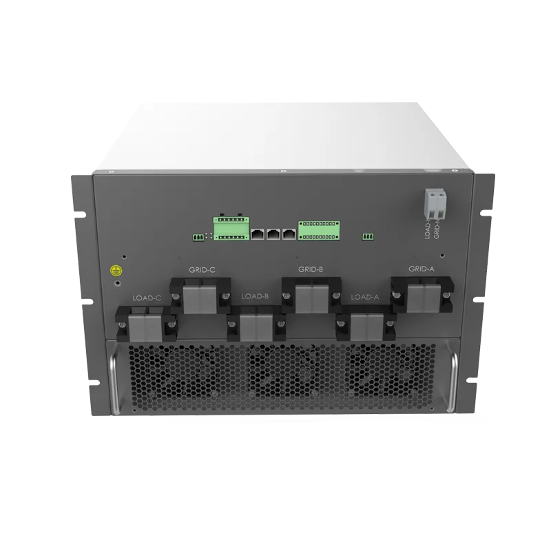
Static transfer switch
- Rated power200 / 400 / 600 kW
- Transfer timebelow 20 ms
- Frequency50/60 Hz, ±5 Hz
- PurposeIsland transfer and load grading
7. Delivery sequence
Grid strength measurement
Fault level, line parameters and historical voltage curves; compute SCR.
Stability study
Model lines, transformers, loads and machines; simulate connected, islanded and faulted cases.
Control tuning
Set inertia constant, droop, virtual impedance and protection limits.
Bench or site testing
Full load, step response and island ride-through with recorded waveforms.
Start-up accompaniment
On site through the first week; refine against real grid behaviour.
8. Frequently asked
How do I know if I need grid-forming?
Compute SCR. Below 3, conventional grid-following units carry real risk; below 2, or with several converters in parallel, go straight to grid-forming.
Can grid-forming cause problems of its own?
Only if parameters are mismatched to the network. We run time-domain studies first, deliver a tuning sheet, and verify with measured waveforms at commissioning to avoid multi-unit oscillation.
How does it live with an existing genset?
Storage handles instantaneous swings and frequency; the genset covers energy and holds its loading band. Coordinated droop means neither fights the other.
Do we need an isolation transformer?
It depends on earthing practice and DC-content requirements. Models with a built-in isolation transformer avoid a separate unit and improve immunity and fault segregation.
Give us your point of connection and we will assess stability
With fault level, line length and load composition we return the SCR calculation, time-domain conclusions and a platform recommendation.
Request a weak-grid proposalNo products in this category yet — product series are being published. Enquire for the full range.